A Pressure Signal Acquisition System Based on Super Capacitor
 Photo by Zhang Tong on Unsplash
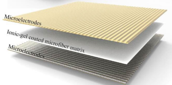
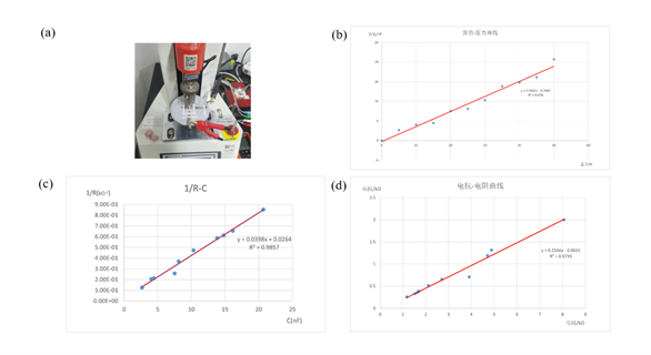
The system is based on a high-sensitivity the electric double-layer capacitor (EDLC) pressure sensing array, which can detect the contact pressure distribution on the robot surface in real time, so as to determine whether a collision has occurred. EDLC consists of an upper and lower electrode layer, and an ionic fibre layer, with the upper and lower electrodes in contact with the middle ionic fibre layer, as shown in Fig. a. Fig. b presents the sensor’s properties using a material test system (MTS, ZQ-990B) and an LCR meter (IM 3536) to perform capacitance response tests on an individual unit (the measuring frequency: 30 kHz, the measuring voltage magnitude: 1.65 V).
The system consists of a pressure sensing matrix, a signal processing unit and a Control Unit. The pressure sensing matrix covers the robot surface and can measure the tiny contact pressure. The signal processing unit includes functions such as analog-to-digital conversion and digital filtering, which can calculate the pressure and distribution in real time. The Control Unit determines the type and direction of collision according to the pressure distribution, and sends emergency stop instructions to control the robot’s movement. The advantage of this system is that it has a sensitive and fast response, which can quickly detect slight contacts; it has a wide coverage and can detect all-round collisions. The work will establish actual prototypes on the robot platform and conduct collision tests to study the pressure laws under different collision conditions.
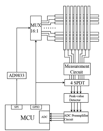
The sensing array obtains the voltage value of each sensing unit by progressive scanning. The MCU communicates with the excitation source circuit AD9833 module using SPI, and inputs the selected rows of the sensing array through a 16:1 multiplexer. The 8 columns of the sensing array obtain the voltage value through the conversion circuit and the four ADC peripherals of the SPDT, peak detection, and ADC pre-signal processing input to the MCU.
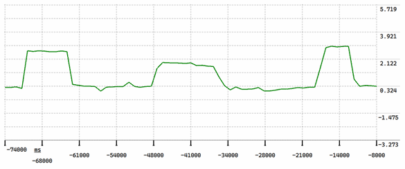
Display the collected pressure signal using the SComAssistant
The PCB is a double-layer board with copper on both sides, divided into analog and digital ground. The MCU used is STM32F4, the main frequency is 84MHz, Flash is 256KB, RAM is 64KB. power input 5V, the digital part is powered by LDO module AMS1117-3.3V, and the analog part is powered by DCDC module A0503S.
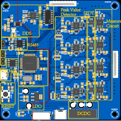
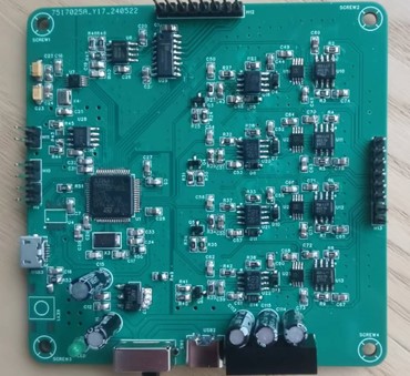
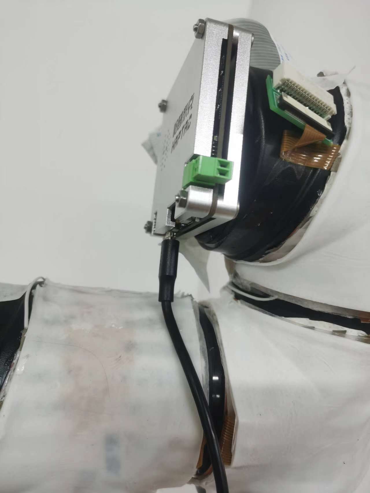
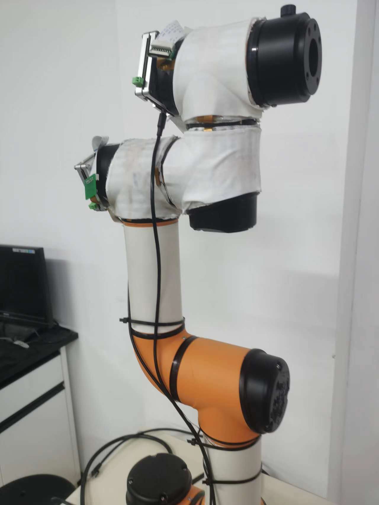
The PCB is mounted as shown.
张通
Student of Mechatronic Engineering
My research interests include control system, robotics technology and micromanipulation.