STM32 communication with AUBO robot using MODBUS RTU
In Modbus communication, the AUBO robot is used as the host and the STM32 is used as the slave.
The robot sends a message to the STM32, requesting to read the hold register, and the corresponding function code is 0X03. STM32 determines whether it is received normally by checking CRC and confirms whether the address code is correct. If it is received normally, it will respond to the AUBO robot.
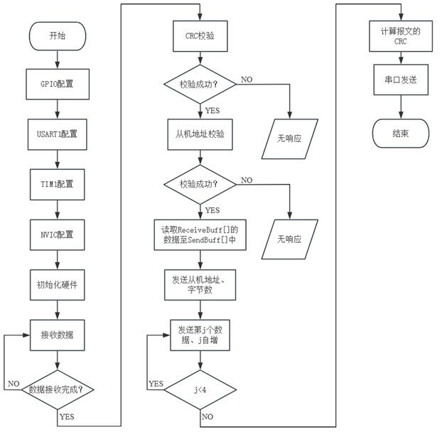
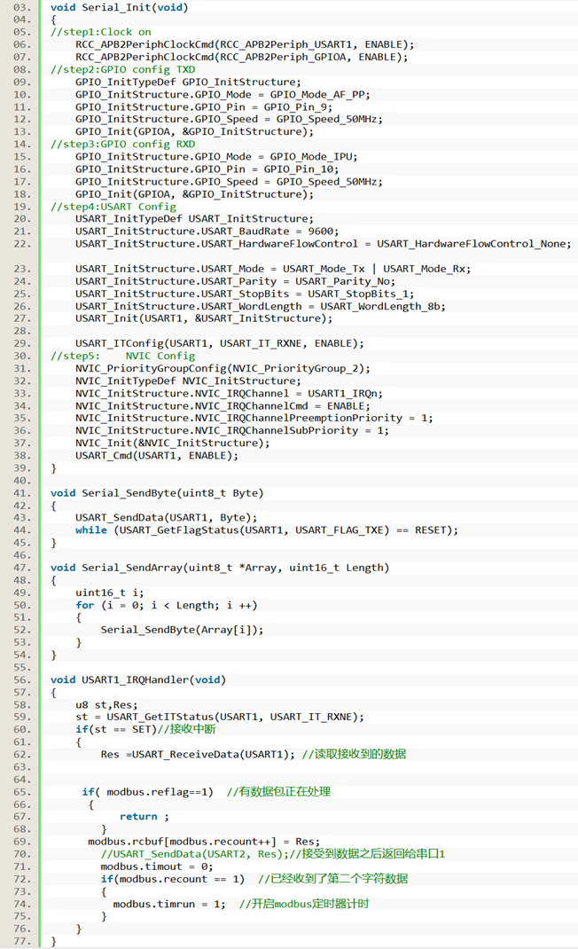
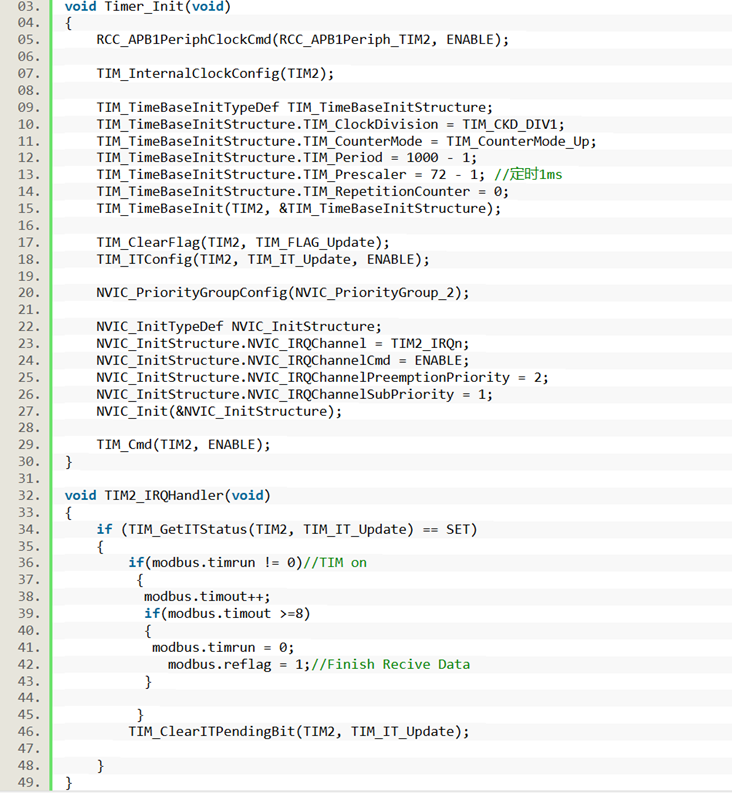
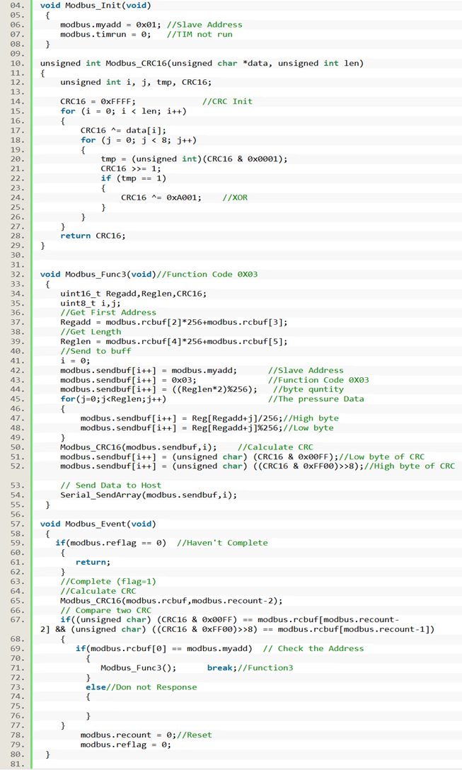
STM32 uses the RS485 interface, and first configures the serial port parameters of USART1. The serial port baud rate is 9600, the data bit is 8, the stop bit is 1, and the check bit is NONE. In order to determine whether the data transmission is completed, a timer interrupt needs to be set. The interrupt time is 1ms, which is counted in the interrupt function. When the timing exceeds 4ms, it is considered that one frame of data reception is completed, the timer flag is reset, and the data processing is started. The address code and function code in the receive buffer ReceiveBuff [] are assigned to the send buffer SendBuff []. According to the received register base address 0X0000 and the number of registers 4, the four pressure signal values of the relay buffer RelayBuff [] are assigned to SendBuff [], and then the CRC code is calculated using the CRC check algorithm. When a frame of data is packaged and sent by serial port, it will answer the host AUBO robot. The code of Modbus part is shown in Appendix E, including serial port configuration, timer configuration, CRC check algorithm, Modbus initialization, and implementation of 03 function functions.
The specific process of Modbus communication is shown in the figure
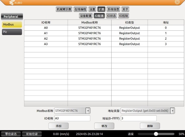
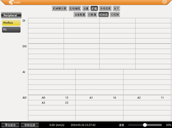
Configure the station number 0X01, baud rate 9600, data bit 8, stop bit 1, and check bit 1 in the master station AUBO. Set four hold registers A0, A1, A2, and A3 of the 0X03 function code in the demonstrator to receive the information transmitted by the slave, as shown in the figures.
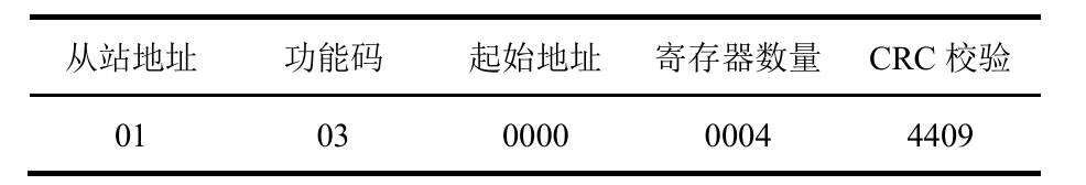
The content of the request sent by the host is as follows. The complete message is 8 bytes, and its format is shown in Table 4.2. One frame of data contains the address of the slave STM32 (0X01), the function code for reading the register (0X03), the start address of the holding register (0X00), the number of registers (0X04), and the automatically generated 16-bit CRC check code. The read register address is 2byte; this address corresponds to the storage address of the buffer array SendBuff [] in STM32.
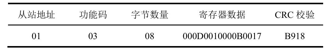
The message replied by the slave is shown in Table 4.3. The complete message is 13 bytes, and one frame of data contains the address of the slave STM32 (0X01), the function code for reading the register (0X03), the number of bytes read (0X08), the register data (0X000D0010000B0017), and the 16-bit CRC check code calculated by the function Modbus_CRC ()
The data received by the robot:
The code for STM32 is as follows:
张通
Student of Mechatronic Engineering
My research interests include control system, robotics technology and micromanipulation.